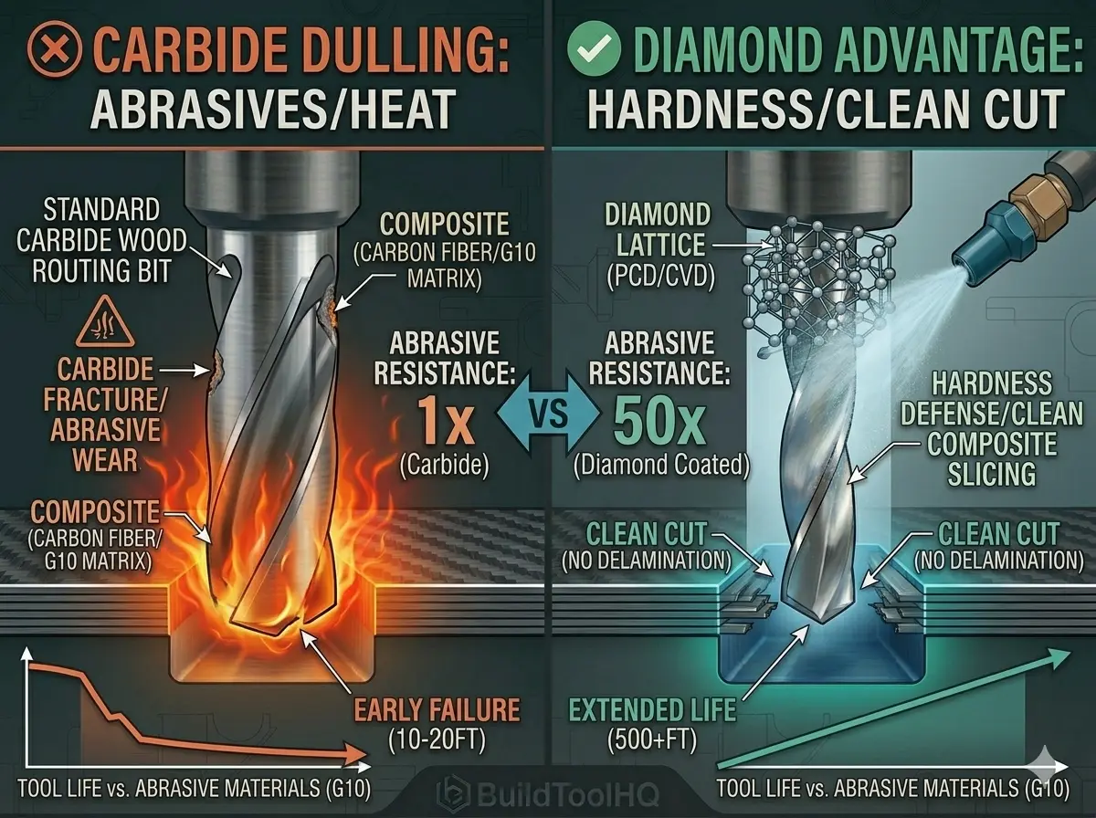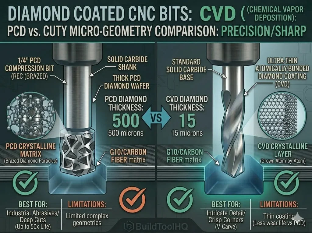
You’ve invested hundreds, perhaps thousands, of dollars into your tooling library. From the high-performance [Upcut vs. Downcut vs. Compression Bits: When to use each for edge finish] that power your roughing passes to the elite [Diamond Coated & Specialized Bits: For composites and abrasive materials] used for aerospace composites, these tools are the heart of your workshop. However, many operators treat bits as disposables. The reality is that the cost of neglect is far higher than the cost of upkeep.
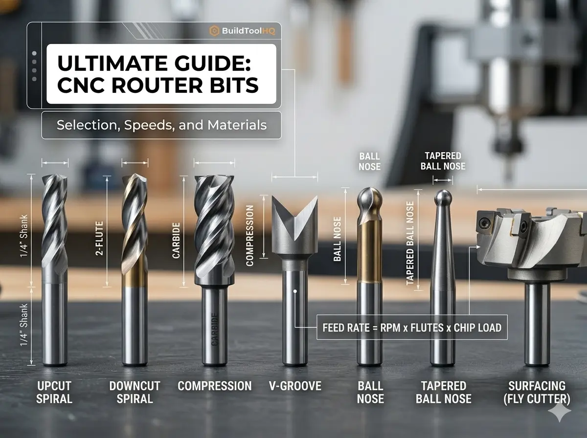
Proper CNC bit maintenance isn’t just about aesthetics; it’s about preventing “runout,” reducing spindle strain, and ensuring your centerpiece projects don’t fail due to a resin-clogged flute. In this comprehensive guide, we’ll cover the chemical, physical, and environmental pillars of tool longevity. This expertise is a core part of our [The Ultimate Guide to CNC Router Bits: Selection, Speeds, and Materials].
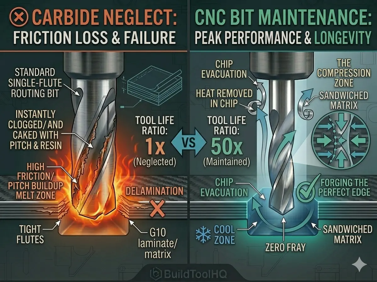
1. The “Resin Trap”: Why Dirty Bits Actually Break
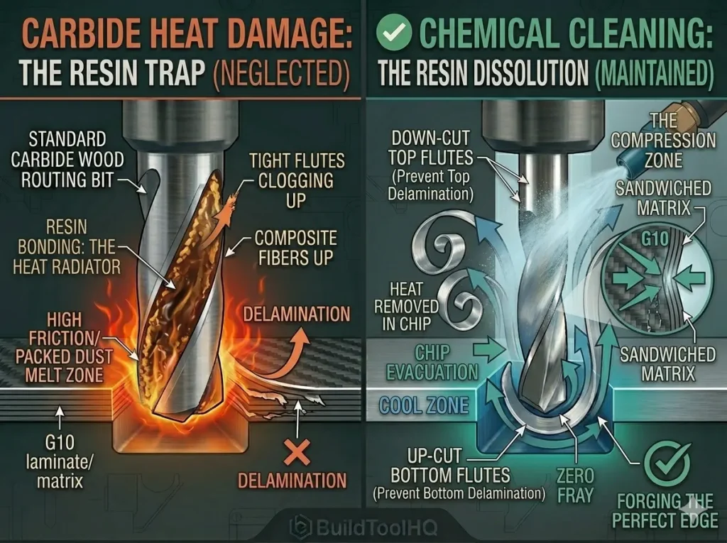
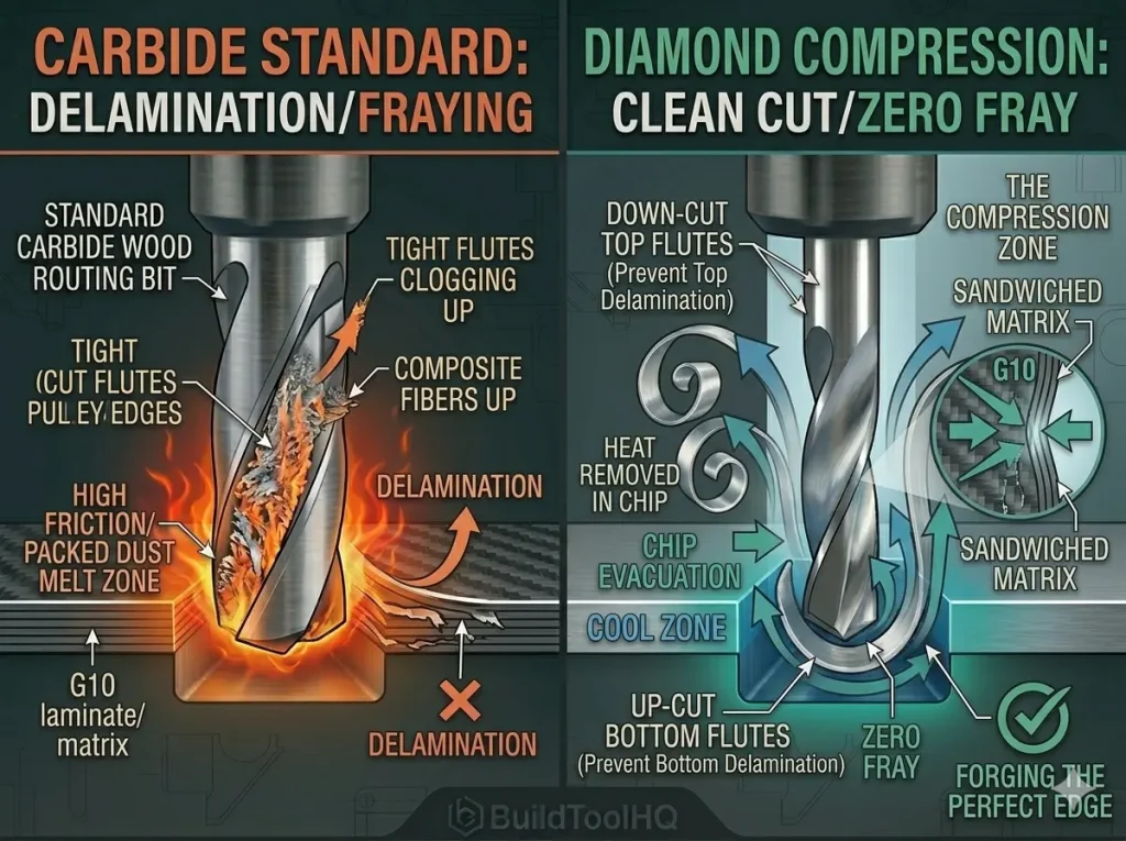
Why compression is king: This technical diagram visualizes the victory. A standard 2-flute bit (left) quickly creates delamination fraying in G10. The diamond coated compression bit (right) uses top-down and bottom-up flutes to create "THE COMPRESSION ZONE." The exploded view (right) shows how this sandwiches the G10 core matrix together with support, allowing the PCD edge (from image_107.png) to slice the supported fibers cleanly, guaranteeing a zero-fray finish in abrasive materials with diamond coated CNC bits.The most common cause of premature tool failure isn’t actually a loss of sharpness—it’s pitch and resin buildup. When you cut softwoods like pine or even dense hardwoods like walnut and cherry, the friction of the cut melts the natural resins in the wood. These resins then bond to the carbide surface, making consistent CNC bit maintenance nearly impossible without intervention.
The Friction Feedback Loop
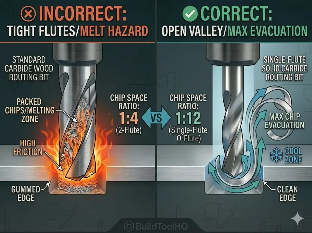
Once resin builds up in the “gullet” (the valley of the flute), it creates a catastrophic feedback loop:
- Increased Friction: The resin creates a sticky surface that prevents chips from sliding out.
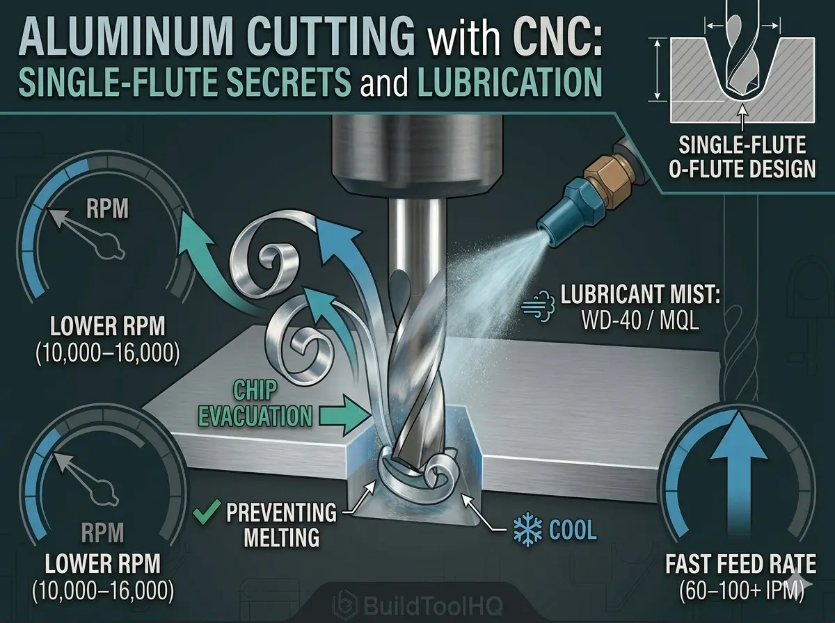
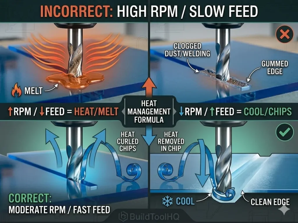
- Heat Spikes: Because chips can’t eject (a principle we emphasize in [Aluminum Cutting with CNC: Single-flute secrets and lubrication]), they get re-cut, generating intense heat.
- Tempering Loss: This heat can eventually reach a point where it compromises the cobalt binder in your carbide, leading to a “cooked” bit that snaps under the slightest load.
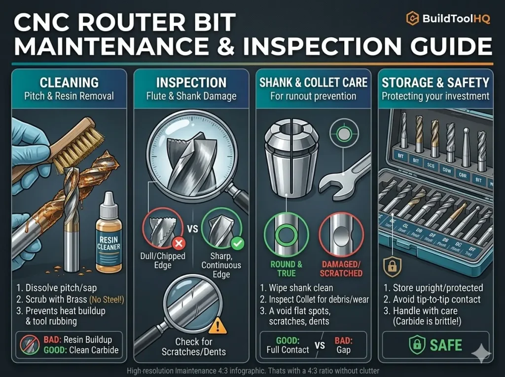
2. The Professional Chemical Cleaning Protocol
To keep your CNC bit maintenance schedule efficient, you need a dedicated cleaning station. Don’t wait for the bit to turn black; clean it as soon as you see a “dull” film forming on the flutes.
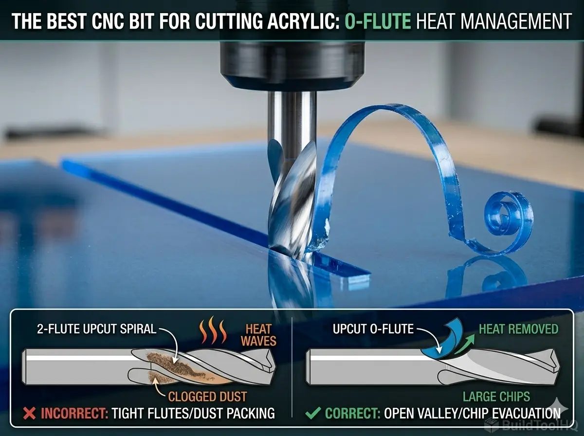
- The Solvent Bath: Submerge the cutting flutes in a non-corrosive solvent. For stubborn melted plastics from [O-Flute Bits for Plastics and Acrylics: Managing heat and preventing melting] runs, use a specialized resin remover.
- The Dwell Time: Let the bits sit for 10–15 minutes. This allows the chemicals to penetrate the bond between the resin and the carbide.
- The Brass Brush: Use a brass-bristled brush. Brass is softer than carbide and will not damage the cutting edge, but it is stiff enough to whisk away softened pitch.
- Immediate Drying: After rinsing, dry the bit with a microfiber cloth and apply a moisture-displacing spray to prevent microscopic oxidation on the edge.
3. The Sharpening Decision: To Hone or to Replace?
A major question in CNC bit maintenance is when to send a tool for professional sharpening.
- Large Diameter Bits: For [Surfacing and Slab Leveling Bits: Mastering large-area clearing] or heavy-duty [Best CNC Bits for Plywood and Hardwoods: A deep dive into wood-specific geometry] tools (1/2″ shank and above), professional sharpening is a high-ROI move.
- Small Diameter Bits: For 1/8″ and 1/4″ bits, the cost of the “setup fee” often exceeds the price of a new high-quality bit.
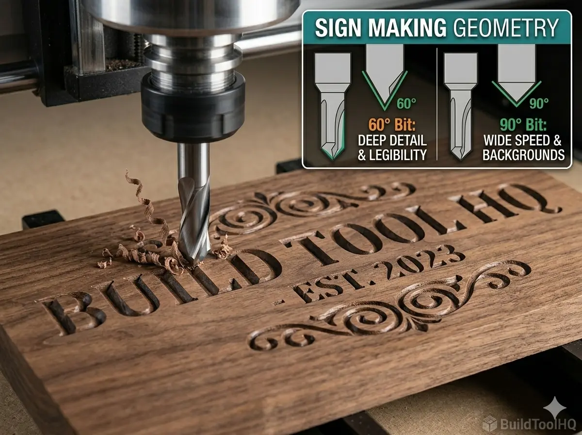
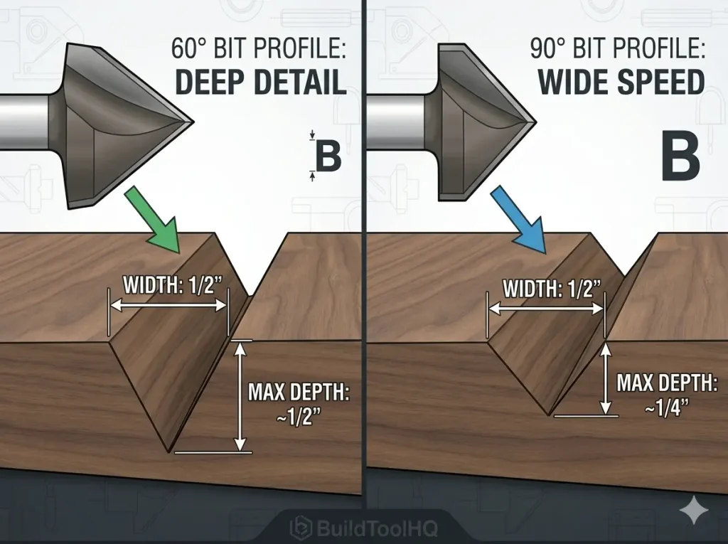
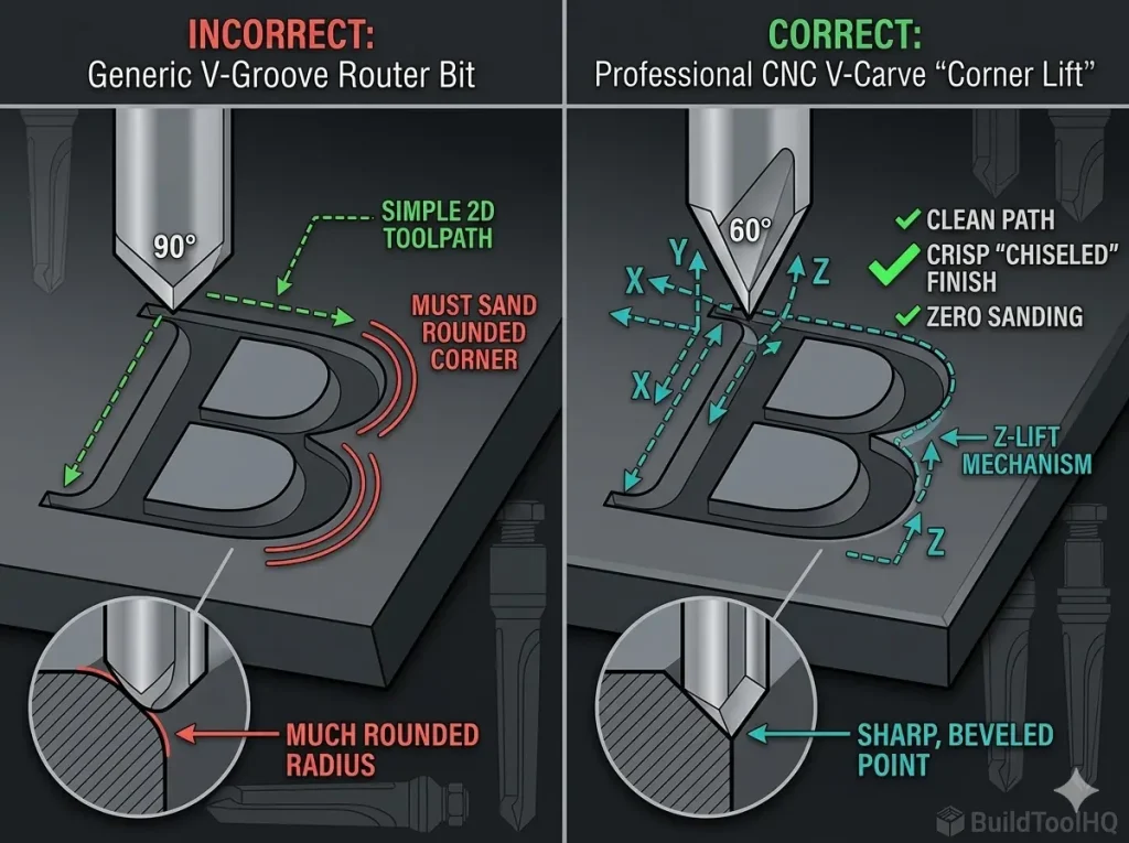
- The V-Bit Dilemma: Because [V-Carve Bits and Sign Making: Achieving crisp detail and sharp corners] rely on a perfect 0.00″ point, hand-sharpening is impossible. If the tip is chipped, the bit is effectively a “roughing only” tool.
- The Diamond Exception: Never attempt to sharpen diamond tools yourself; they require specialized EDM processing.
4. Proper Storage: The “No-Touch” Rule
Carbide’s greatest strength (hardness) is its greatest weakness (brittleness). If you keep your bits in a loose drawer where they can clink together, the edges are effectively “hammering” each other, leading to micro-fractures. Effective CNC bit maintenance requires a vertical storage block where no two cutting edges can touch.
Climate-Controlled Tooling
If your CNC is in a garage, humidity is your enemy. Store your primary bit collection in a weather-sealed “dry box” with silica gel packs. This prevents the “pitting” of the carbide surface that occurs in high-moisture environments, a step often overlooked in standard CNC bit maintenance routines.
5. Collet Maintenance: The “Silent Killer” of Bits
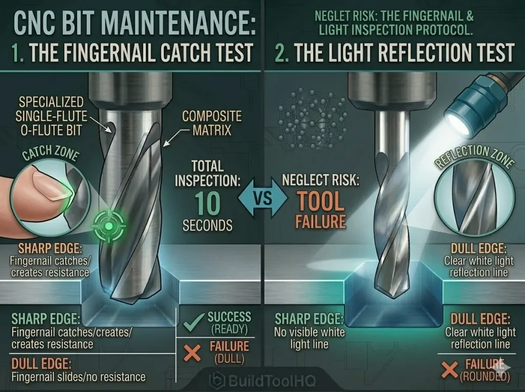
Understanding sharpness: This diagram visualizes the critical 10-second inspection protocol. By mastering (left) the Fingernail Catch Test (where a sharp edge must catch the nail) and (right) the Light Reflection Test (where a sharp edge shows a dark line with no reflection, as seen in image_115.png), you prevent cutting with dull bits, which kill professional results and destroy the expensive toolsYou can have a perfectly clean bit, but if your collet is dirty, you will experience runout (the bit spinning off-center). Even 0.001″ of runout can reduce tool life by 50% by putting uneven pressure on the flutes.
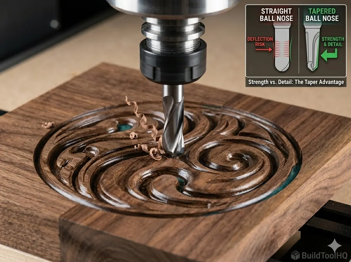
As part of your CNC bit maintenance routine, blow out the collet and the spindle taper with compressed air every time you change a bit. Replace your primary collets every 400–600 hours of run time to ensure a perfect “grip” on your precision [Ball Nose vs. Tapered Ball Nose: The nuances of 3D carving and finishing passes].
6. Pre-Flight Visual Inspection (The 10-Second Test)
Before hitting “Cycle Start,” perform these three CNC bit maintenance checks:
- The Fingernail Test: Gently drag your nail across the edge (away from the point). If it slides without “biting,” the tool is dull.
- The Color Check: Look for “bluing.” If the carbide has a blue or purple tint, the bit has exceeded its thermal limits and is now “softened.”
- The Shank Check: Look for circular scratches, which mean your bit was spinning inside the collet, leading to massive heat buildup.
7.Strategic Maintenance for Heavy Clearance Tools
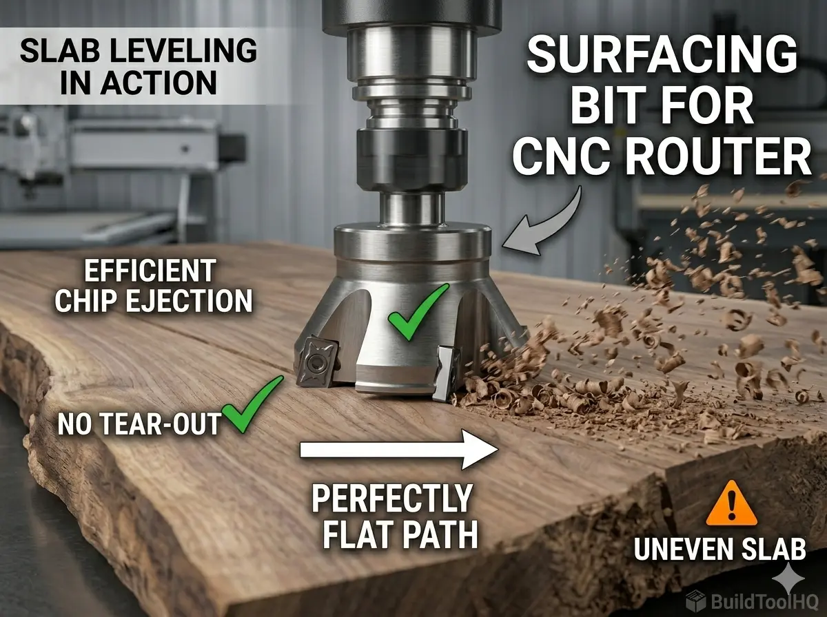
Many users forget that CNC bit maintenance applies most critically to their largest tools. After leveling a massive slab, your [Surfacing bit for CNC router] will have accumulated significant resin due to the sheer volume of material removed.
Cleaning the removable carbide inserts on these bits is far more cost-effective than allowing them to dull prematurely. By integrating this into your CNC bit maintenance workflow, you ensure your leveling passes remain glass-smooth without the “burn lines” associated with dirty cutters.
Conclusion: Turning Maintenance into Profit
Consider investing in tools that aid in your CNC Bit Maintenance process for improved efficiency.
A disciplined CNC bit maintenance routine can double or triple the lifespan of your tooling. By treating your bits as precision scientific instruments rather than consumables, you ensure that every cut is as clean as the first and that your machine remains a profitable, high-precision asset.
Frequently Asked Questions
Effective CNC Bit Maintenance includes regular inspections to catch potential issues early.
How often should I clean my CNC bits?
You should clean your CNC bits as soon as you notice a visible “film” or dark residue on the flutes. For materials like pine or plywood, this may be after every 2–4 hours of run time. For plastics or aluminum, clean them immediately if you notice any “gumming” to prevent permanent heat damage.
Can I use WD-40 to clean my CNC router bits?
WD-40 is excellent as a post-cleaning moisture displacer, but it is not a dedicated resin solvent. For CNC bit maintenance, use a specialized pitch and resin remover or a concentrated degreaser like Simple Green to break down the organic bonds of wood resin without damaging the carbide.
How do I know if my CNC bit is too dull to use?
Perform the “Fingernail Test”: gently drag your nail across the cutting edge. If it slides smoothly without catching, the bit is dull. Other signs include “bluing” of the carbide (indicating over-heating), increased spindle noise, or fuzzy/burned edges on your workpiece.
Is it worth it to sharpen small 1/4″ carbide CNC bits?
Generally, no. The cost of professional sharpening for a 1/8″ or 1/4″ bit often equals or exceeds the cost of a new high-quality tool. Sharpening is best reserved for large-diameter surfacing bits or custom profiles where the replacement cost is over $50–$100.
Can diamond coated CNC bits be sharpened at home?
No. (Diamond coated CNC bits) require specialized Electrical Discharge Machining (EDM) to sharpen because diamond is harder than any standard grinding wheel. Attempting to sharpen these at home will destroy the microscopic diamond lattice and ruin the tool.