If you have ever watched a CNC machine effortlessly “grow” a 3D portrait or a topographical map out of a solid block of wood, you have witnessed the power of rounded-tip geometry. But for the professional maker, a critical question arises: Ball nose vs. tapered ball nose—which one actually belongs in your tool changer?
This deep dive is a core component of our comprehensive master guide: [The Ultimate Guide to CNC Router Bits: Selection, Speeds, and Materials].While [Surfacing and Slab Leveling Bits: Mastering large-area clearing] prepare the flat canvas and [V-Carve Bits and Sign Making: Achieving crisp detail and sharp corners] handle the lettering, the ball nose family is responsible for organic, flowing contours. Choosing the wrong one doesn’t just result in a poor finish; it often results in snapped bits and hours of unnecessary sanding.
1. Defining the Geometry: What is a Ball Nose Bit?
A standard ball nose bit is a cylindrical tool with a perfectly hemispherical tip. Its geometry is designed to create a rounded groove or “cove.” In 3D machining, these bits are used for “Finishing Passes,” where the tool follows the Z-axis height map of a 3D model.
The Problem with Straight-Shank Ball Noses
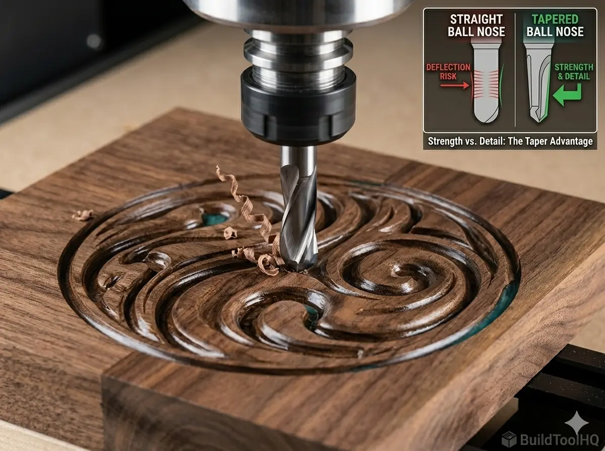
The primary limitation of a standard ball nose is its structural integrity. If you are carving a high-detail 3D relief, you might need a tip as small as 1.5mm. In a standard ball nose, the entire shaft of the tool is 1.5mm thick. At 18,000 RPM, these tiny “needles” are incredibly prone to deflection (bending).
When the bit bends, it creates “chatter” marks on the wood. Even worse, if it encounters a hard knot or an aggressive feed rate, the carbide will fatigue and snap instantly at the collet. This is a level of fragility you won’t find when using [Upcut vs. Downcut vs. Compression Bits: When to use each for edge finish].
2. The Tapered Ball Nose: The 3D Carving Hero
The tapered ball nose was engineered specifically to solve the “broken bit” problem in 3D wood carving. Instead of a thin cylinder, it features a thick, sturdy shank (usually 6mm or 1/4″) that “tapers” down at a specific angle (typically 3.8° or 5.4°) to a tiny, pinpoint tip.
The Physics of Strength (Polar Moment of Inertia)
By using a tapered body, the bit gains massive lateral strength. In physics terms, increasing the diameter of the tool toward the shank exponentially increases its resistance to bending. This rigidity allows you to increase your Feed Rate—sometimes by as much as 40%—without risking a tool break. This is the “BuildToolHQ” secret to finishing long 3D jobs faster. Achieving this level of stability is as critical as the chip-clearing logic found in [Aluminum Cutting with CNC: Single-flute secrets and lubrication].
3. Ball Nose vs. Tapered Ball Nose: The Key Nuances
The smoothness of your finish is determined by your Stepover. When comparing ball nose vs. tapered ball nose for your next project, consider these professional factors:
A. Reach and Clearance
Tapered bits are superior for deep carvings. Because the bit gets wider as it goes up, the “shoulder” of the tool is less likely to rub against the vertical walls of a deep pocket compared to a straight-shank bit. However, the taper itself requires more horizontal clearance at the top of the cut.
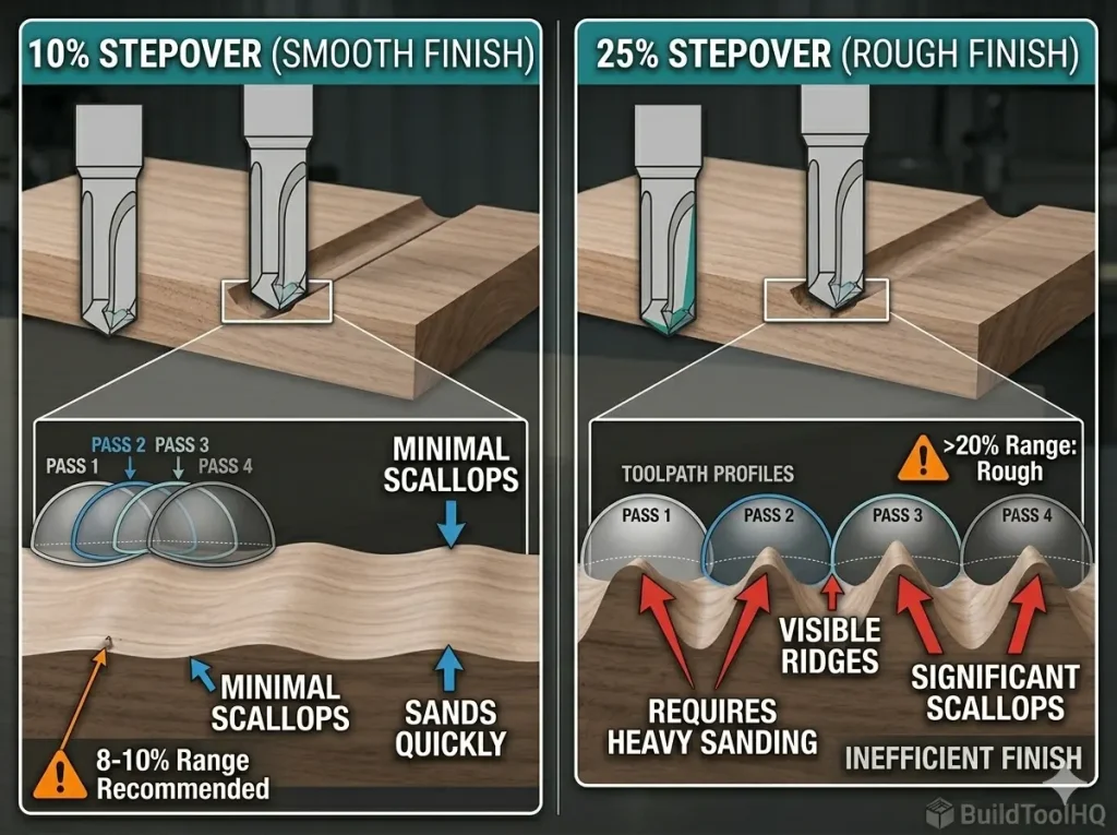
B. The “Scallop” Effect and Stepover
Both tools leave behind “scallops”—tiny ridges between each horizontal pass.
- The Rule of Thumb: For a professional 3D finish, a stepover of 8% to 10% of the tip diameter is the sweet spot.
- Diminishing Returns: Dropping below 8% adds hours to your machine time with almost no visible improvement in surface quality.
C. Material Interaction
- Hardwood (Walnut, Oak): The density of these woods creates high lateral pressure. The tapered ball nose is essential here to prevent chatter.
- Epoxy Resin: When leveling 3D river tables, heat is the enemy. Tapered bits have more mass, allowing them to dissipate heat better than thin straight bits, preventing the resin from melting—a concept also covered in our guide on [O-Flute Bits for Plastics and Acrylics: Managing heat and preventing melting].
- Plywood: As discussed in our guide on [Best CNC Bits for Plywood and Hardwoods: A deep dive into wood-specific geometry], clean cuts are difficult. A sharp tapered ball nose slices the cross-grain layers more effectively.
4. The Professional 3D Workflow
To achieve a “sand-free” finish, you should never rely on a single tool. Follow this three-step process:
- The Roughing Pass: Use a 1/4″ upcut spiral bit to remove the bulk of the material. Set a “Machining Allowance” of 0.5mm.
- The Finishing Pass: This is where the ball nose vs tapered ball nose debate is settled. Use the tapered bit with a 10% stepover.
- The Rest Machining Pass: If your model has tiny crevices that a 1.5mm bit can’t reach, run a final pass with a 0.25mm tapered bit.
Pro Tip: Always verify that your spoilboard is perfectly flat using a [Surfacing bit for CNC router] before starting a long 3D carve.
5. Setting Up Your Software (The Taper Angle Trap)
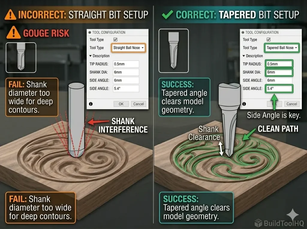
The most common mistake when switching to a tapered ball nose is failing to update your tool database. If your software thinks you are using a straight bit, but you are using a tapered one, the machine will “gouge” the top of your model as the wider taper moves through a tight space.
Required Data Points for CAM:
- Tip Radius: Half the tip diameter (e.g., 0.5mm radius for a 1mm bit).
- Side Angle: The specific degree of the taper (usually 3.8°, 5.4°, or 6.2°).
- Clearance Diameter: The diameter of the shank.
6. Maintenance: Protecting Your 3D Assets
3D carving passes can run for 6 to 12 hours. This sustained friction generates heat that can dull carbide.
- Resin Buildup: Softwoods and resins leave “pitch” on the flutes. Clean your bits according to our [CNC Bit Maintenance: Sharpening, cleaning, and storage for longevity] protocols.
- Check for “Galling”: If cutting metals or abrasive composites, look for material welding to the tip, as described in [Diamond Coated & Specialized Bits: For composites and abrasive materials].
Frequently Asked Questions (FAQ)
Can I use a straight ball nose bit for roughing passes?
No. Using standard, small-diameter straight ball nose bits for roughing passes is highly inefficient. They are not designed to remove bulk material. Instead, you should always perform a preliminary “Roughing Pass” with a (flat-bottom upcut spiral bit) to remove most of the material in steps. This leaves just a thin (0.5mm) skin of material for the tapered ball nose to clean up.
How do I input a tapered bit into VCarve, Fusion 360, or Vectric software?
This is the “Taper Angle Trap” discussed in Section 5. You cannot simply select “Ball Nose” for a tapered bit. Most CAM software requires you to explicitly set the “Tool Type” to “Tapered Ball Nose.” In the settings, you must input the Tip Radius (half the diameter), the Shank Diameter (e.g., 6mm), and the correct Side Angle (typically 3.8° or 5.4°). Failing to add the angle will cause the bit to gouge your 3D model.
Will a tapered ball nose bit help with epoxy river tables?
Yes. Tapered bits are excellent for leveling 3D epoxy surfaces or cutting detailed channels for “inlays” within resin. Because a tapered bit has more mass than a straight bit, it dissipates heat far more effectively. This is crucial for cutting plastics, as excessive heat will melt the epoxy rather than slicing it, gumming up the bit flutes.
How do I choose the right tip radius for my 3D carving?
Choosing the right tip radius (0.25mm, 0.5mm, 1mm) is a balance between detail and machine time. A tiny 0.25mm tapered bit can carve intricate facial features, but requires a very low stepover (e.g., 8%), which makes the cutting pass take hours. For standard 3D relief carvings or topographical maps, a 0.5mm or 1mm tip radius is usually the best professional compromise, providing clean detail without excessive machining time.